
In IT THINKS, the behavior of chip inputs and outputs hinges on how circuit connections are mapped. The game automatically determines inputs by checking for unconnected pins in your circuit setup, which can catch players by surprise. Learning how to organize your inputs and effectively merge them is crucial for building efficient chips.
In this article, I’ll break down how the game identifies chip inputs and outputs, how to use a Split 2 to help manage multiplexer inputs, and tips for merging inputs to streamline your circuits. It’s easy to waste time misinterpreting input assignments if you’re not careful, so let’s get into the details.
Before diving in, make sure to experiment with different circuit designs in a sandbox area. It’s a great way to get familiar with how chips function before tackling larger projects!
Chip Inputs and Outputs in IT THINKS!
1: 3-input AND chip
The game starts calculating the number of inputs by identifying any unconnected inputs present in your circuit. Each unconnected input is marked as a separate input alongside the corresponding outputs.
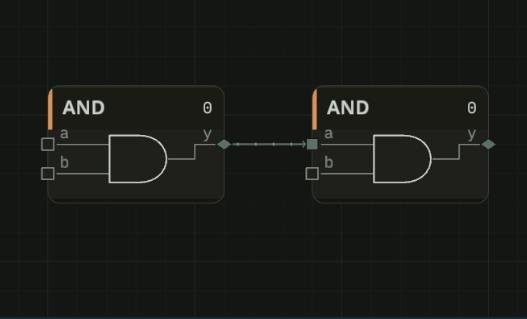
When I click Cast A Chip, I get three inputs: in1, in2, and in3, with one output: out1.
2: 4:1 Multiplexer
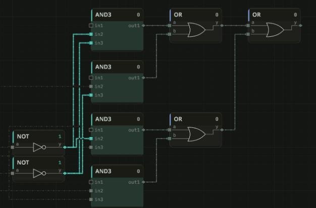
I’ve got a sample 4-input, 1-output multiplexer. However, after casting this chip, I unexpectedly find that it gives me…
Six inputs appear instead! This came as a surprise, and it means you’ll need to experiment beforehand to fully understand what you’ll get.
To handle these additional inputs better, especially since we can’t rename pins on cast chips yet, I’m exploring ways to organize them efficiently.
By adding a Split 2 component, I can unify the select input and condense it into a 2-bit word:
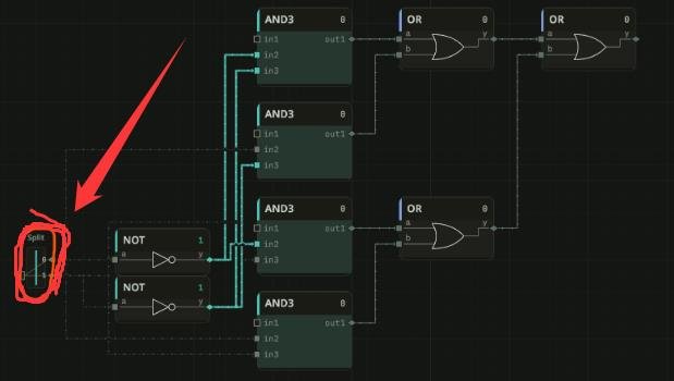
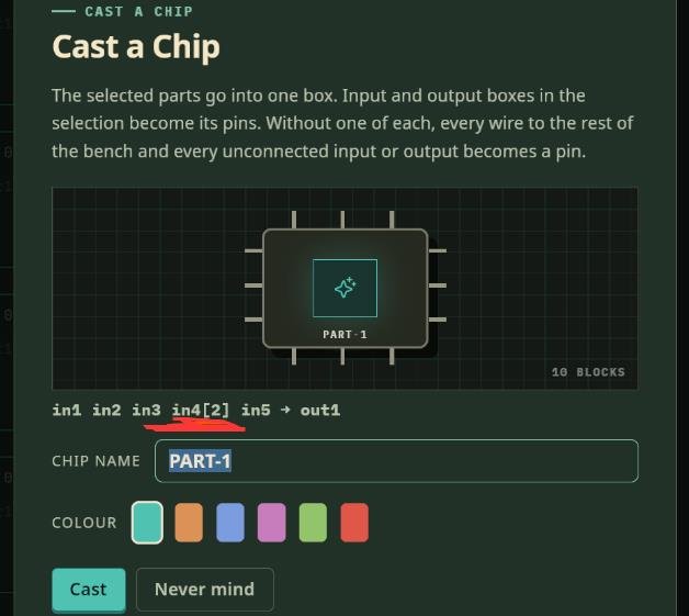
Based on my observations, it looks like the game labels inputs from in1 to inN according to their position, likely going from top to bottom and then left to right.
After moving the Split 2 to the bottom, I see that the 2-bit input is now designated as in5[2].
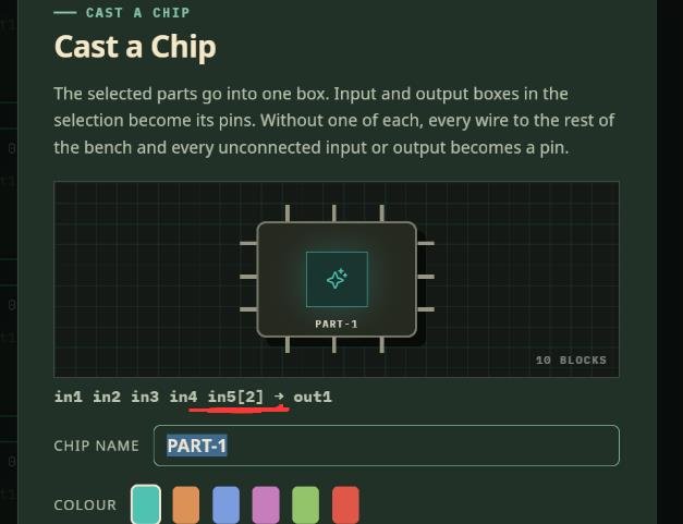
How I merge or unify inputs
When I need to merge multiple inputs, for instance, making in1 to in4 share one value, I can connect any component to all of them.
In this scenario, I’m using a NOT gate that connects to each of the in1 inputs:
A key part of this setup is that I do NOT SELECT the NOT gate intended for unification.
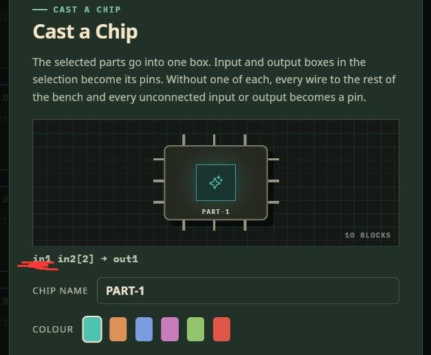
After clicking Cast A Chip, all these inputs will merge into a single input called in1.